Sponsored by Lockheed Martin, the American Council on Renewable Energy (ACORE) is now an official partner with NASCAR Green, enabling Lockheed Martin and ACORE to promote renewable energy, sustainability, energy security and efficiency to an audience of more than 100 million NASCAR fans. Through this partnership, the organizations will motivate and inspire the next generation of scientists, technologists and engineers through promoting careers in science, technology, engineering and math (STEM).
According to a new research report published by Allied Market Research (Portland, OR), the global market for quantum dots (QDs) reached $316 million in 2013 and is expected to grow to $5.04 billion by 2020 at a compound annual growth rate (CAGR) of 29.9% in the period between 2014 and 2020.
However, the volume consumption will grow at a much faster rate of 116.5% during the same period, to reach 72 tons in 2020 — the result of a drop in QD price over time, attributable to the refinement of mass-production processes and high volume demand.
The report is called “Quantum Dot (QD) Market–Global Analysis, Growth, Trends, Opportunities, Size, Share and Forecast through 2020.”
Key drivers for growth of the QD market are efficient conversion of solar energy into power, the rising use of display devices, and utility in multiple applications, according to the report. Display and lighting-equipment manufacturers are eager to bring out QD-based products, which are currently the prime driver of QD market growth.
QD light emitters will be big
As for end-use categories, QD light-emitting devices will have the highest CAGR of 39% between now and 2020, says the report; other categories with lesser CAGRs include QD displays, lasers, chips, sensors, medical devices, and photovoltaics.
And as for materials, indium arsenide (InAs) QDs will have a leading market share of $1.18 billion in 2020, with cadmium selenide (CdSe), cadmium sulfide (CdS), cadmium telluride (CdTe), and silicon (Si) all runners-up.
Optoelectronics will lead revenue share at $1.77 billion in 2020, with other contenders being quantum optics, QD-based security and surveillance, renewable energy, and biological/healthcare imaging.
“The QD display market is set to grow exponentially as many companies such as Sony Corp., LG Display, etc. are getting into alliances with QD technology providers to commercialize QD displays, especially TV sets,” note analysts Shreyas Naidu and Priyanka Gotsurve. “QD technology enhances the color display by at least 50% and it is also an energy efficient technology.”
Some factors, such as high cost of technology and slow adoption due to extended research, are currently slowing market growth, although the growth of mass manufacturing and bulk purchasing will quickly negate the cost constraints. Further penetration of the technology in newer applications such as security and defense, food, and packaging will provide the essential future growth thrust to the market. Future use of newer and more cost effective materials will give QDs an added competitive edge over other materials such as organic dyes.
Among geographic markets, North America has the highest revenue share due to early adoption. The region is expected to grow consistently and attain revenue of $1.92 billion by 2020.However, the Asia-Pacific market is expected to have the highest CAGR of 30.4% for the 2013-2020 analysis period.
Background
Quantum dot is small semiconductor in crystal format that is used in business verticals that use display and monitor devices and many other types of equipment. Global Nano-optimized market is expected to reach 3 trillion by 2015. Increasing demand for optimized devices with better performance and resolution quality is a major driving force to adopt quantum dot technology into various application areas. Brightness of quantum dots is 10-20 times higher than organic dyes. As the semiconductor material shrinks to quantum-dot level, it helps in altering the light wavelength material and covert material from insulator to conductor.
Quantum dot is semiconductor that can be used for different devices instead of searching for new semiconductor with special chemical composition. Major application market for quantum dot is Display and Monitor as quantum dots are used in LED. However, the process of manufacturing Blue quantum dots in size that is smaller than average is very difficult over other colors of quantum dots, this is acting as major limiting factor to adopt quantum dots in display and monitor products. Despite of few disadvantages, quantum dots are going to capture attention by major players, but it is very difficult for manufacturers to analyze potential application market of quantum dots. This report covers potential application segment and revenue generated by each segment. The global QD market is expected to grow from $316 million in 2013 to $5,040 million ($5.04 Billion) in 2020 at a CAGR of 29.9% for the analysis period (2013-2020).
Global QD market by application
The QD market is segmented into various applications such as biological imaging, optoelectronics, quantum optics, security & surveillance, and renewable energy. The biological imaging market is the most mature market in terms of revenue and it is expected to have consistent growth in the market. However, the optoelectronics application is expected to have the highest growth potential for the analysis period 2013 and 2020. The renewable energy application is the next fastest growing application in the QD market.
Global QD market by devices
The quantum dot based devices are the end-users of the technology as these particles are used to develop devices for various applications. The end-user segment consists of QD Medical Devices, QD LCD and LED Display Devices, QD Laser Devices, QD Photovoltaic Devices, QD Chip, QD Sensors, and QD LED Lighting Devices. The QD based medical devices currently have the highest market share as medical scientists have been engaged in developing these devices for more than two decades. However, the display devices are expected to have the highest growth rate in the QD market, as the technology enhances the color quality of display devices and saves energy. Photovoltaic devices are expected to have the second highest growth rate after display devices.
Global QD market by technology
QDs are produced by using various technologies such as colloidal synthesis, fabrication, viral assembly, electrochemical assembly, bulk manufacturing and cadmium free QD technology. Colloidal synthesis is the most popular technology in the market currently, as it has the potential to produce QDs at a large scale. However, it is expected that bulk manufacturing would have the highest revenue share with the highest growth rate due to its ability of large scale QD production with better quality. The cadmium free QD technology is expected to have the second highest growth, as it would be used in consumer applications, since cadmium has restrictions for use in these applications.
Global QD market by material
QDs are produced by processing some materials such as Cadmium Selenide, Cadmium Sulphide, Cadmium Telluride, Indium Arsenide, and Silicon. Cadmium Selenide was the most commonly used material to produce QDs in 2013 followed by Cadmium Sulfide, as these were the first materials that were ever used in the process. However, Indium Arsenide would have the highest growth rate for the analysis period 2013-2020 along with the highest revenue by 2020. The silicon material would have the second highest growth rate as it is observed that the light emission capacity of silicon is in excess of 70% and can be used in electronic devices to increase efficiency.
Global QD market by geography
The QD market is geographically segmented into North America, Europe, Asia-Pacific and Rest of the World (RoW). Currently, North America has the highest revenue share in the market followed by Europe due to early adoption of the QD technology. However, for the analysis period of 2012-2020, it is expected that the Asia-Pacific region would have the highest growth rate followed by the RoW region.
Global QD market competitive analysis
Key Companies profiles included in this report are Sony Corporation; Altair Nanotechnology,Inc; Evident Technologies, LG Display, Life Technologies Corporation, Microvision Inc; Quantum Material Corporation; Samsung Electronics Co. Ltd, Nexxus Lighting Microvision Inc. The companies have opted for partnerships and collaborations as a key strategy so that they can share the expertise to develop better QD based products and solutions, as it is an evolving technology.
Global QD market high level analysis
The report analyses the potency of suppliers and buyers along with threats of new entrants and substitute products based on the Porter’s five force analysis. The report also analyses the impact of the drivers, restraints and opportunities of the market as per the current market trends and projected future scenario. The key investment pockets are analyzed in the report based on the growth estimations of the application segment.
Reason for doing the study
The commercial prospects of the market are inclined towards growth due to the efficiency of QDs to produce energy efficient and flexible products and solutions. The market is currently at a pre-commercialized stage and the report covers the research efforts undertaken to commercialize the market. The market estimation are made on the basis of some assumptions of the past years volume production and expected production in the future and projected price fluctuations. The report gives a deep dive-analysis on applications in various sectors of the market to give market players an understanding about the important growth potential to maximize profits. The report also studies the impact and penetration of the QD technology in various geographic regions so that companies can understand end-user preferences to gain competitive advantage.
Key Benefits
This report analyses the factors that are driving and limiting the growth of the market
Market estimations are done according to the market trends for the period 2013-2020
Analysis of key strategies adopted by market players through their press releases would assist in providing in-depth understanding of the market intelligence
Deep-dive analysis of various geographies would give an understanding of the trends in various regions so that companies can make region specific plans
In-depth analysis of segments such as applications, end-users (devices), technologies and materials provide insights that would allow companies to gain competitive edge
The courtyard between MIT.nano and Building 4 looking west from Building 8 toward the Great Dome. Image: Wilson Architects
Starting in 2018, researchers from across MIT will be able to take advantage of comprehensive facilities for nanoscale research in a new building to be constructed at the very heart of the Cambridge campus.
The 200,000-square-foot building, called “MIT.nano,” will house state-of-the-art cleanroom, imaging, and prototyping facilities supporting research with nanoscale materials and processes—in fields including energy, health, life sciences, quantum sciences, electronics, and manufacturing. An estimated 2,000 MIT researchers may ultimately make use of the building, says electrical engineering professor Vladimir Bulović, faculty lead on the MIT.nano project and associate dean for innovation in the School of Engineering.
“MIT.nano will sit at the heart of our campus, and it will be central to fulfilling MIT’s mission in research, education, and impact,” says MIT President L. Rafael Reif. “The capabilities it provides and the interdisciplinary community it inspires will keep MIT at the forefront of discovery and innovation, and give us the power to solve urgent global challenges. By following the lead of faculty and student interest, MIT has a long tradition of placing bold bets on strategic future technologies, and we expect MIT.nano to pay off in the same way, for MIT and for the world.”
MIT.nano will house two interconnected floors of cleanroom laboratories containing fabrication spaces and materials growth laboratories, greatly expanding the Institute’s capacity for research involving components that are measured in billionths of a meter—a scale at which cleanliness is paramount, as even a single speck of dust vastly exceeds the nanoscale. The building will also include the “quietest” space on campus—a floor optimized for low vibration and minimal electromagnetic interference, dedicated to advanced imaging technologies—and a floor of teaching laboratory space. Finally, the facility will feature an innovative teaching and research space, known as a Computer-Aided Visualization Environment (CAVE), allowing high-resolution views of nanoscale features.
“The tools of nanotechnology will play a critical part in how many engineering disciplines solve the problems of the 21st century, and MIT.nano will shape the Institute’s role in these advances,” says Ian A. Waitz, dean of the School of Engineering and the Jerome C. Hunsaker Professor of Aeronautics and Astronautics. “This project represents one of the largest commitments to research in MIT’s history. MIT.nano will carry the last two decades of research into new realms of application and discovery.”
“Usually we talk about how science enables new technology, but discovery is a two-way street,” adds Maria Zuber, MIT’s vice president for research and the E.A. Griswold Professor of Geophysics. “In MIT.nano, technology will advance basic science through the extraordinary observations that will be possible in this state-of-the-art facility.”
MIT.nano will be a 200,000-square-foot research facility for nanoscale research constructed at the very heart of the MIT campus. The building will house state-of-the-art cleanroom, imaging, and prototyping facilities supporting research with nanoscale materials and processes—in fields including energy, health, life sciences, quantum sciences, electronics, and manufacturing.
The four-level MIT.nano will replace the existing Building 12, and will retain its number, occupying a space alongside the iconic Great Dome. It will be interconnected with neighboring buildings, and accessible from MIT’s Infinite Corridor—meaning, Bulović says, that the new facility will be just a short walk from the numerous departments that will use its tools.
“This building needs to be centrally located, because nanoscale research is now central to so many disciplines,” says Bulović, who is the Fariborz Maseeh Professor in Emerging Technology at MIT.
Users of the new facility, he adds, are expected to come from more than 150 research groups at MIT. They will include, for example, scientists who are working on methods to “print” parts of human organs for transplantation; who are creating superhydrophobic surfaces to boost power-plant efficiency; who work with nanofluids to design new means of locomotion for machines, or new methods for purifying water; who aim to transform the manufacturing of pharmaceuticals; and who are using nanotechnology to reduce the carbon footprint of concrete, the world’s most ubiquitous building material.
The research that will take place in MIT.nano could also help the world meet its growing energy needs, Bulović says. For example, cloud computing already consumes 1.3% of the world’s electricity; as this technology proliferates, its energy use is projected to grow a thousandfold over the coming decade. Hardware based on nanoscale switching elements—a new technology now being pursued by MIT researchers—could prove crucial in reducing the energy footprint of cloud computing.
“But we have many urgent challenges that existing technology cannot address,” Bulović says. “If we want to make sweeping change—more than incremental progress—in the most urgent technical areas, we need this building and the tools of nanoscience and nanotechnology housed within it.”
“The need for advanced facilities to support nanoscale research was identified in 2011 as the Institute’s highest academic priority as part of the MIT 2030 process to envision how our campus might evolve to meet future needs for research and education,” says Israel Ruiz, MIT’s executive vice president and treasurer. “It is wonderful to see we are boldly moving to accomplish our goal.”
Cleanroom facilities, by their nature, are among the most energy-intensive buildings to operate: Enormous air-handling machinery is needed to keep their air filtered to an extraordinarily high standard. Travis Wanat, the senior project manager at MIT who is overseeing the MIT.nano project, explains that while ventilation systems for ordinary offices or classrooms are designed to exchange the air two to six times per hour, cleanroom ventilation typically requires a full exchange 250 times an hour. The fans and filters necessary to handle this volume of air require an entire dedicated floor above each floor of cleanrooms in MIT.nano.
But MIT.nano will incorporate many energy-saving features: Richard Amster, director of campus engineering and construction, has partnered with Julie Newman, MIT’s director of sustainability. Together, they are working within MIT, as well as with the design and contracting teams, “to develop the most efficient building possible for cleanroom research and imaging,” Amster says.
Toward that end, MIT.nano will use heat-recovery systems on the building’s exhaust vents. The building will also be able to sense the local cleanroom environment and adjust the need for air exchange, dramatically reducing MIT.nano’s energy consumption. Dozens of other features aim to improve the building’s efficiency and sustainability.
Despite MIT.nano’s central location, the floor devoted to advanced imaging technology will have “more quiet space than anywhere on campus,” Bulović says: The facility is situated as far as possible from the noise of city streets and subway and train lines that flank MIT’s campus.
Indeed, protection from these sources of noise and mechanical vibration dictated the building’s location, from among five campus sites that were considered. According to national standards on ambient vibration, Bulović says, parts of MIT.nano will rate two levels better than the standard typically used for such high-quality imaging spaces.
Another important goal of the building’s design—by Wilson Architects in Boston—is the creation of environments that foster interactions among users, including those from different disciplines. The building’s location at a major campus “crossroads,” its extensive use of glass walls that allow views into lab and cleanroom areas, and its soaring lobbies and other common areas are all intended to help foster such interactions.
“Nanoscale research is inherently interdisciplinary, and this building was designed to encourage collaboration,” Bulović says.
“MIT’s enduring leadership in technology and science is made possible by the interconnective nature of our community, and our total potential is greater than the sum of our parts,” adds Timothy Swager, the John D. MacArthur Professor of Chemistry. “At an intellectual level this is driven by our collective commitment to excellence and innovation, but the physical proximity of researchers at MIT is the heart and soul of this special atmosphere. MIT.nano will serve to enhance these interactions and provide an opportunity-rich venue where chemistry, biology, physics, and engineering all converge to create devices and understanding that will empower MIT researchers to reach new heights in innovation.”
The choice of MIT.nano’s central location is not without compromise, Bulović says: There is very limited access to the construction site—only three access roads, each with limited headroom—so planning for the activities of construction and delivery vehicles, and for the demolition of the current Building 12 and construction of MIT.nano, will present a host of logistical challenges. “It’s like building a ship in a bottle,” Bulović says.
But addressing those challenges will ultimately be well worth it, he says, pointing out that an estimated one-quarter of MIT’s graduate students and 20 percent of its researchers will make use of the facility. The new building “signifies the centrality of nanotechnology and nanomanufacturing for the needs of the 21st century. It will be a key innovation hub for the campus.”
All current occupants of Building 12 will be relocated by June, when underground facilities work, to enable building construction, will commence; at that point, fences will be erected around the constriction zone. The existing Building 12 will be demolished in spring 2015 and construction of MIT.nano is slated to begin in summer 2015.
A new study from Los Alamos National Laboratory and the University of Milano-Bicocca demonstrates that superior light-emitting properties of quantum dots can be applied in solar energy, boosting the output of solar cells and allowing for the integration of photovoltaic-active architectural elements into buildings.
A house window that doubles as a solar panel could be on the horizon, thanks to recent quantum-dot work by Los Alamos National Laboratory researchers in collaboration with scientists from University of Milano-Bicocca (UNIMIB), Italy. Their project demonstrates that superior light-emitting properties of quantum dots can be applied in solar energy by helping more efficiently harvest sunlight.
This schematic shows how the quantum dots are embedded in the plastic matrix and capture sunlight to improve solar panel efficiency.
“The key accomplishment is the demonstration of large-area luminescent solar concentrators that use a new generation of specially engineered quantum dots,” said lead researcher Victor Klimov of the Center for Advanced Solar Photophysics (CASP) at Los Alamos.
Quantum dots are ultra-small bits of semiconductor matter that can be synthesized with nearly atomic precision via modern methods of colloidal chemistry. Their emission color can be tuned by simply varying their dimensions. Color tunability is combined with high emission efficiencies approaching 100 percent. These properties have recently become the basis of a new technology – quantum dot displays – employed, for example, in the newest generation of the Kindle Fire e-reader.
Light-harvesting antennas
A luminescent solar concentrator (LSC) is a photon management device, representing a slab of transparent material that contains highly efficient emitters such as dye molecules or quantum dots. Sunlight absorbed in the slab is re-radiated at longer wavelengths and guided towards the slab edge equipped with a solar cell.
Klimov explained, “The LSC serves as a light-harvesting antenna which concentrates solar radiation collected from a large area onto a much smaller solar cell, and this increases its power output.”
“LSCs are especially attractive because in addition to gains in efficiency, they can enable new interesting concepts such as photovoltaic windows that can transform house facades into large-area energy generation units,” said Sergio Brovelli, who worked at Los Alamos until 2012 and is now a faculty member at UNIMIB.
Because of highly efficient, color-tunable emission and solution processability, quantum dots are attractive materials for use in inexpensive, large-area LSCs. One challenge, however, is an overlap between emission and absorption bands in the dots, which leads to significant light losses due to the dots re-absorbing some of the light they produce.
“Giant” but still tiny, engineered dots
To overcome this problem the Los Alamos and UNIMIB researchers have developed LSCs based on quantum dots with artificially induced large separation between emission and absorption bands (called a large Stokes shift).
These “Stokes-shift” engineered quantum dots represent cadmium selenide/cadmium sulfide (CdSe/CdS) structures in which light absorption is dominated by an ultra-thick outer shell of CdS, while emission occurs from the inner core of a narrower-gap CdSe. The separation of light-absorption and light-emission functions between the two different parts of the nanostructure results in a large spectral shift of emission with respect to absorption, which greatly reduces losses to re-absorption.
To implement this concept, Los Alamos researchers created a series of thick-shell (so-called “giant”) CdSe/CdS quantum dots, which were incorporated by their Italian partners into large slabs (sized in tens of centimeters) of polymethylmethacrylate (PMMA). While being large by quantum dot standards, the active particles are still tiny – only about hundred angstroms across. For comparison, a human hair is about 500,000 angstroms wide.
“A key to the success of this project was the use of a modified industrial method of cell-casting, we developed at UNIMIB Materials Science Department” said Francesco Meinardi, professor of Physics at UNIMIB.
Spectroscopic measurements indicated virtually no losses to re-absorption on distances of tens of centimeters. Further, tests using simulated solar radiation demonstrated high photon harvesting efficiencies of approximately 10% per absorbed photon achievable in nearly transparent samples, perfectly suited for utilization as photovoltaic windows.
Despite their high transparency, the fabricated structures showed significant enhancement of solar flux with the concentration factor of more than four. These exciting results indicate that “Stokes-shift-engineered” quantum dots represent a promising materials platform. It may enable the creation of solution processable large-area LSCs with independently tunable emission and absorption spectra.
Funding: The Center for Advanced Solar Photophyscis (CASP) is an Energy Frontier Research Center funded by the Office of Science of the US Department of Energy.
The work of the UNIMIB team was conducted within the UNIMIB Department of Materials Science and funded by Fondazione Cariplo (2012-0844) and the European Community’s Seventh Framework Programme (FP7/2007-2013; grant agreement no. 324603).
Publication: Francesco Meinardi, et al., “Large-area luminescent solar concentrators based on ‘Stokes-shift-engineered’ nanocrystals in a mass-polymerized PMMA matrix,” Nature Photonics (2014); doi:10.1038/nphoton.2014.54
Quantum dots, a technology with significant potential in optical applications and energy efficiency, is incredibly expensive and complicated to manufacture. This fact alone would be enough to keep this high potential technology out of industry use. In addition to such obstacles, conventional chemical synthesis of QDs must occur at high temperatures using toxic solvents, making waste removal a challenge. However, QDs can be used to advance medical imaging, light emitting diodes, and solar cells in commercial applications.
A process invented by Lehigh University Chemical Engineering professor Bryan Berger now allows for the manufacturing of quantum dots in a safer way and at a fraction of the cost. Whereas in conventional production techniques QDs could cost over $10,000 per gram, this manufacturing technique cuts that cost to about $1 per gram. Enabling a larger scale of production makes QDs a viable technology for use in commercial applications.
Learn more about Berger’s Facile, High Yield Synthesis and Purification of CdS Quantum Dots from Optimized Strains of S. Maltophelia on Lehigh’s Technology Publisher.
Quantum dots, a technology with significant potential in optical applications and energy efficiency, is incredibly expensive and complicated to manufacture. This fact alone would be enough to keep this high potential technology out of industry use. In addition to such obstacles, conventional chemical synthesis of QDs must occur at high temperatures using toxic solvents, making waste removal a challenge. However, QDs can be used to advance medical imaging, light emitting diodes, and solar cells in commercial applications.
A process invented by Lehigh University Chemical Engineering professor Bryan Berger now allows for the manufacturing of quantum dots in a safer way and at a fraction of the cost. Whereas in conventional production techniques QDs could cost over $10,000 per gram, this manufacturing technique cuts that cost to about $1 per gram. Enabling a larger scale of production makes QDs a viable technology for use in commercial applications.
(Nanowerk Spotlight) The unique properties of nanomaterials are beneficial in applications to remove pollutants from the environment. The extremely small size of nanomaterial particles creates a large surface area in relation to their volume, which makes them highly reactive, compared to non-nano forms of the same materials.
The potential impact areas for nanotechnology in water applications are divided into three categories:
Silver, iron, gold, titanium oxides and iron oxides are some of the commonly used nanoscale metals and metal oxides cited by the researchers that can be used in environmental remediation (read more: “Overview of nanomaterials for cleaning up the environment”).
A more recent entrant into this nanomaterial arsenal is graphene. Individual graphene sheets and their functionalized derivatives have been used to remove metal ions and organic pollutants from water. These graphene-based nanomaterials show quite high adsorption performance as adsorbents. However they also cause additional cost because the removal of these adsorbent materials after usage is difficult and there is the risk of secondary environmental pollution unless the nanomaterials are collected completely after usage. One solution to this problem would be the assembly of individual sheets into three-dimensional (3D) macroscopic structures which would preserve the unique properties of individual graphene sheets, and offer easy collecting and recycling after water remediation.
Although great progress has been achieved in both preparation of bulky graphene porous architectures and their application in water remediation, much work remains to be done. A recent review article in the March 12, 2014, online edition of Small (“Porous Graphene Materials for Water Remediation”) summarizes the recent developments in this area. In particularly, the article focuses on the rational design and application of bulky graphene materials in the cleanup of oil, removal of heavy metal ions, and elimination of water-soluble organic pollutants.
The authors also suggest future prospects of bulky graphene materials for environmental remediation. The application of graphene-based bulky porous architectures in water remediation greatly depends on their surface properties and microstructure, such as the spacing size among graphene sheets and their orientation. While a variety of graphene porous architectures have been successfully obtained by different methods, most of their microstructure is disordered and random. Ordered and controllable microstructures and surface design would effectively improve the performance of graphene porous architectures in water remediation.
Clean-up of oil Bulky porous materials based on graphene and its derivatives exhibit highly selective adsorption ability of oil from aqueous solution due to their high specific surface area and superhydrophobic-oleophilic surface. Furthermore, they can be easily utilized during the oil cleanup process and collected after usage. In addition to easy manipulation, they show excellent recycling ability.
One challenge in fabricating bulky graphene materials for oil cleanup is to achieve a porous architecture while at the same time keeping a large accessible surface area of 2D graphene sheets. Leavening strategy, a process to produce porous structures by in situ gas formation, was developed to form reduced graphene oxide (rGO) foams with open porous and continuous crosslink structures by autoclaved leavening and steaming of graphene oxide layered films (read more: “Making graphene ‘bread’ – leavening technique results in freestanding graphene oxide films”).
In addition to pure graphene materials, graphene composites and carbon aerogels can serve as an adsorbent to clean up oil from water.
Removal of heavy metal ions Various materials, such as clay minerals, oxides, zeolites, and carbon materials, have been used as adsorbents to remove heavy metal ions from water. Unfortunately, their relatively low adsorption capacity, poor chemical stability as well as unsatisfactory recycling ability limit their practical application. Different from the demand of oil cleanup, the adsorption capability of adsorbent materials for heavy metal ions depends on their specific surface area and the interactions between them and heavy metal ions.
Therefore, favorable porous structure and active graphene surface are required in the design of bulky graphene materials for selective adsorption of heavy metal ions from water. These rationally designed bulky graphene materials exhibited excellent adsorption capacity as well as recycling ability. Elimination of water-soluble organic pollutants A number of adsorbent materials, such as mesoporous silica, mesoporous hybrid aerogel and activated carbon, have been used as adsorbents for elimination of water soluble organic pollutants.
However, these adsorbents often suffer from either low/limited adsorption capacity or inefficient desorption; moreover, almost all of them lack the ability of recycling and reuse. Alternatively, recent work has illustrated that bulky porous graphene materials shows high adsorption capacity and excellent recycling ability. Like the requirement for removal of heavy metal ions, specific surface area and the interactions between graphene and water soluble organic pollutants are the two main factors that determine the adsorption and desorption capacity of porous graphene architectures for water soluble organic pollutants. Apart from the adsorption capacity, the recycling ability of graphene-based adsorbent materials is another key parameter for their practical application in water remediation. An ideal adsorbent should not only possess high adsorption capability, but also show good desorption property.
In order to recycle porous graphene materials, desorption of pollutants from them should be considered. One major advantage of the porous graphene materials is their structural and chemical stability, thus, they can be regenerated after each use by desorbing pollutants from them. The authors conclude that graphene-based composites comprising multiple materials will greatly extend the scope of graphene’s functionality far beyond what pure graphene materials have already been achieved in water remediation application. Therefore, new approaches that control the assembly of graphene and other functional materials into macroscopic hybrid architectures are desired. They point out that many issues such as low-cost, scale-up, high recyclability should be also considered in the preparation of bulky graphene porous architectures and their applications in environmental remediation.
(Nanowerk Spotlight) Concern about the depletion of global water resources has grown rapidly in the past decade due to our increasing global population and growing demand for other diverse applications.
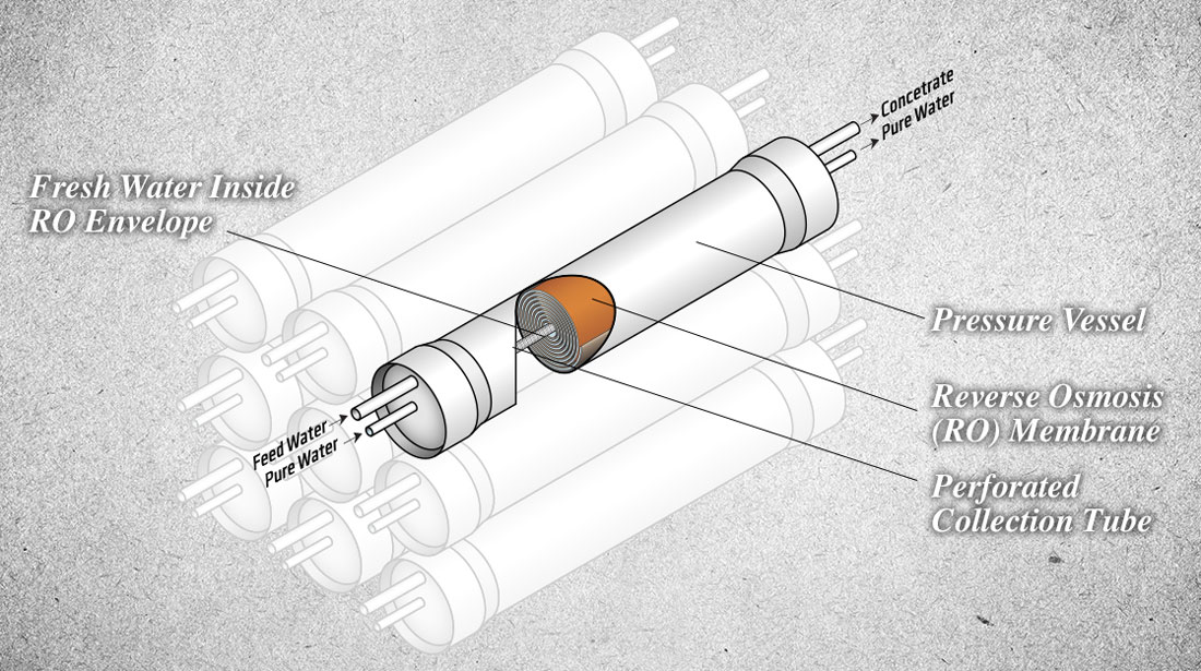
Since only 2.5% of the Earth’s water is fresh, it has been reported that almost half of the world’s population is at risk of a water crisis by the year 2025 [1]. Accordingly, significant research efforts have been focused on the desalination of brackish/seawater and the remediation and reuse of wastewater to meet the agricultural, industrial, and domestic water demands. While much progress has been made, the advent of membrane desalination techniques over fifty years ago has given significant impetus to the advancement of water purification technology. However, the need for improved membrane performance and lower operating costs have been a barrier for both researchers and consumers alike. Current water treatment technology Water purification membranes are typically divided into four categories according to pore size:
– microfiltration (MF, < few microns)
– ultrafiltration (UF, < 100 nm)
– nanofiltration (NF, < 10 nm)
– reverse osmosis (RO, < 1 nm)
Feed water quality is an important consideration when selecting a suitable membrane. NF and RO membranes have typically been designed for use of brackish water (2-5 g/L of salt), seawater (35 g/L of salt), and waste water (from agriculture and industry) treatments due to their separation capacity of ions (mono-/di-valent) and organic materials (macromolecules, proteins, glucose, and amino acids) from the water.
Of the various candidate materials, conventional desalination membranes are mainly fabricated using aromatic polyamide (PA) thin film composites on a polysulfone support and Loeb-Sourirajan-type cellulose acetate (CA) membranes to create desired architecture.
CA membranes exhibit a specific water flux of 1-20 L/m2/day/bar with an average NaCl rejection of > 98%. The advantage of CA membranes is that they are easy-to-make, fairly well priced, and offer excellent stability against mechanical stress and chlorine. However, an inherent weakness of CA membranes is their performance decrease due to changes in pH, temperature, hydrolysis, and fouling.
(click image to enlarge)
PA membranes on the other hand exhibit a high flux (20-200 L/m2/day/bar) with a high salt rejection (> 99%) as well as increased stability against a wide range of pH and temperature. Unfortunately, despite having benefits, the extremely low resistance to chlorine and membrane fouling are construed as major obstacles for PA membranes. As a result, PA membranes are rendered uneconomical because of the high cost of pre-treatment steps prior to desalination membranes.
Most current desalination technologies on the market are based on energy-intensive processes such as multi-stage flash distillation (MSF; 35 kWh/m3) or a pressure-driven RO membranes (> 3 kWh/m3 for seawater and < 1 kWh/m3 for brackish water).
While membrane-based technology is more cost-effective than heat-based technology, the high cost for installation, operation, and maintenance are still major constraining factors for general use of membrane technologies in water treatment.
These costs (> 0.5 $/m3 for seawater and 0.2-0.3 $/m3 for brackish water [2]) are higher than the costs of obtaining fresh water from other sources. Furthermore, it has been predicted that current membrane technology is approaching the maximum performance achievable from CA and PA-based materials [3]. Considering that water treatment costs are directly related to the membrane performance, there is an increasing demand for innovative solutions that move beyond the modification of conventional materials, in order to meet scientific and economic requirements.
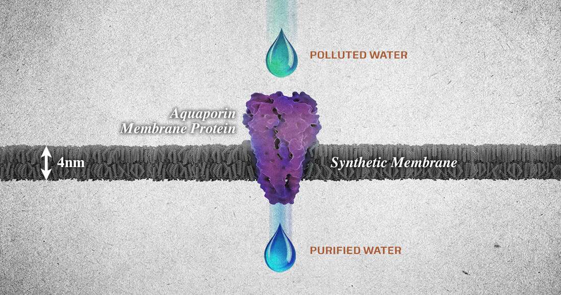
Aquaporin-embedded biomimetic membrane At Ingenuity Lab in Edmonton, Alberta, Dr. Carlo Montemagno and a team of world-class researchers have been investigating plausible solutions to existing water purification challenges. They are building on Dr. Montemagno’s earlier patented discoveries by using a naturally-existing water channel protein as the functional unit in water purification membranes [4].
(click image to enlarge)
Aquaporins are water-transport proteins that play an important osmoregulation role in living organisms [5]. These proteins boast exceptionally high water permeability (~ 1010 water molecules/s), high selectivity for pure water molecules, and a low energy cost, which make aquaporin-embedded membrane well suited as an alternative to conventional RO membranes. Unlike synthetic polymeric membranes, which are driven by the high pressure-induced diffusion of water through size selective pores, this technology utilizes the biological osmosis mechanism to control the flow of water in cellular systems at low energy.
In nature, the direction of osmotic water flow is determined by the osmotic pressure difference between compartments, i.e. water flows toward higher osmotic pressure compartment (salty solution or contaminated water). This direction can however be reversed by applying a pressure to the salty solution (i.e., RO).
The principle of RO is based on the semipermeable characteristics of the separating membrane, which allows the transport of only water molecules depending on the direction of osmotic gradient. Therefore, as envisioned in the recent publication
the core of Ingenuity Lab’s approach is to control the direction of water flow through aquaporin channels with a minimum level of pressure and to use aquaporin-embedded biomimetic membranes as an alternative to conventional RO membranes.
Ingenuity Lab’s ongoing research efforts Although introduced a decade ago, only recently has the proof-of-concept for aquaporin-based water purification membranes been demonstrated. Their ultimate success depends on improved membrane performance and membrane functionality which is affected by:
1) Activity of aquaporin in the membrane (rate of water transport)
2) Design concept of the protein-incorporated membrane matrix
3) Membrane manufacturability.
Since aquaporin-incorporated membranes are the key component to attaining higher levels of salt rejection and water flux, Ingenuity Lab has two intense research efforts underway.
The first is to improve the quality and properties of the materials used to produce aquaporin-based membranes. Both the production yield and the stability of the aquaporin is being improved through genetic modification. Additionally, new materials are being developed for use as the matrix to house the aquaporin molecules and form stable, biocompatible membranes that provide structural support for the protein and eliminate leakage around the protein. Efficient production of functional aquaporin and biomimetic materials with optimal protein compatibility guarantees the highest level of water purification capacity, which adds maximum economic benefits to the invention.
Ingenuity Lab’s second major research effort focuses on the development of new methods for assembling and fabricating water purification membranes using novel design concepts. The goal of this task is to develop a platform which protects aquaporin from mechanical and chemical stresses, while maintaining functionality, enabling low cost, scalable production.
The work being done at Ingenuity Lab holds great promise for our generation and those to come. Ingenuity Lab’s water purification membranes will be applied to treat wastewater and seawater at a much lower pressure than current membranes. The low-energy requirement and high water flow rate of aquaporins are essential components to the realization of cost-effective water purification membranes. In addition to enhanced energy efficiency, unconventional manufacturability-driven membrane design contributes to cost-competitiveness, setting the membranes apart from traditional, more expensive, desalination processes.
In a unique approach, Ingenuity Lab is applying technology and expertise from a variety of disciplines to actively solve some of the world’s most pressing environmental challenges; including here in Alberta, where this technology could be used to reduce the environmental impact of withdrawing bitumen from the oil sands. By reducing the environmental impact of oil sands mining it will allow us to continue to utilize this valuable resource for years to come.
References [1] Kulshreshtha, S. N. A global outlook for water resources to the year 2025. Water Resour. Manag. 1998, 12(3), 167-184. [2] Fritzmann, C.; Löwenberg, J.; Wintgens, T.; Melin T. State-of-the-art of reverse osmosis desalination. Desalination. 2007, 216, 1-76. [3] Elimelech, M.; Phillip, W.A. The future of seawater desalination: energy, technology, and the environment. Science. 2011, 333(6043), 712-717. [4] Montemagno, C.D.; Schmidt, J.J.; Tozzi, S.P. Biomimetic Membranes. U.S. Patent 7,208,089 B2, 24 April 2007. [5] Borgnia, M.; Nielsen, S.; Engel, A.; Agre, P. Cellular and molecular biology of the aquaporin water channels. Annu. Rev. Biochem. 1999, 68, 425–458.
It may seem strange to hear the words “fracking” and “environmentally friendly” in the same sentence.
After all, hydraulic fracturing, or fracking, in which high-pressure chemically treated water is used to crack rock formations and release trapped oil and gas, is a dirty term to many environmentalists. Critics decry the practice for consuming vast amounts of fresh water, creating toxic liquid waste, and adding to the atmosphere’s greenhouse gas burden, mostly because of increased risk of leaks of the potent heat-trapping gas, methane. (See related quiz, “What You Don’t Know About Natural Gas.”)
James Hill, chief executive of the Calgary, Alberta-based energy services firm GasFrac, is one of a handful of technology pioneers determined to change that. Hill’s company has introduced a new fracking method that uses no water at all. Instead, GasFrac uses a gel made from propane—a hydrocarbon that’s already naturally present underground—and a combination of what it says are relatively benign chemicals, such as magnesium oxide and ferric sulfate, a chemical used in water treatment plants. Over the past few years, GasFrac has used the process 2,500 times at 700 wells in Canada and the United States.
“We’re actually using hydrocarbons to produce hydrocarbons,” Hill said. “It’s a cycle that’s more sustainable.”
GasFrac is one of a growing number of companies, including giant GE and the oil services firm Halliburton, that are pioneering technological improvements to mitigate some of the environmental downsides to the process that has spurred a North American energy boom. (See Interactive, “Breaking Fuel From Rock.”) Besides GasFrac’s water-free method, other companies are working on ways to use recycled frack water or non-potable brine in fracking. Some are working on replacing harsh chemicals used in the process with more benign mixtures, or to cleanse water that’s been used in fracking. Other innovators are looking to replace diesel-powered drilling equipment with engines or motors powered by natural gas or solar energy, and to find ways to find and seal leaks that allow methane, a potent greenhouse gas, to escape.
Such efforts have even won cautious support from some environmental activists, who’ve decided that it may be more realistic to mitigate the consequences of fracking than to fight its use.
Here are a few of the efforts to make fracking greener:
Water-Free Fracking: GasFrac’s fracking system, which uses a gelled fluid containing propane, has other advantages besides eliminating the need for water, according to Hill. Because the gel retains sand better than water, it’s possible to get the same results with one-eighth the liquid and to pump at a slower rate. Because GasFrac says the amount of hydrocarbon in the gel is comparable to what’s in the ground, the fluid can simply merge into the flow being extracted from the ground, eliminating the need to drain contaminated wastewater and haul it away in trucks for disposal, usually at deep-well injection sites. “We present a much smaller footprint,” he said. (See related, “Fracking Waste Wells Linked to Ohio Earthquakes.”)
Using Recycled Water or Brine: While fracking typically uses freshwater, industry researchers have worked to perfect friction-reducing additives that would allow operators to use recycled “gray” water or brine pumped from underground. Halliburton’s UniStim, which went on the market about a year ago, can create a highly viscous fluid from any quality of water, according to Stephen Ingram, the company’s technology manager for North America. In northeastern Canada, one producer has tapped into a deep subsurface saline water aquifer for a portion of its supplies for hydraulic fracturing.
Eliminating Diesel Fumes: The diesel-powered equipment used in drilling and pumping wells can be a worrisome source of harmful pollutants such as particulates, as well as carbon emissions that contribute to global warming. And diesel fuel is expensive. Last year, Apache, a Houston-based oil and gas operator, announced it would become the first company to power an entire fracking job with engines using natural gas. In addition to reducing emissions, the company cut its fuel costs by 40 percent. Halliburton has introduced another innovation, the SandCastle vertical storage silo for the sand used in fracking, which is powered by solar panels. The company also has developed natural-gas-powered pump trucks, which Ingram said can reduce diesel consumption on a site by 60 to 70 percent, resulting in “a sizable reduction in both emissions and cost.”
PHOTOGRAPH BY DENNIS DIMICK, NATIONAL GEOGRAPHIC
Drainage water pours into a settling pond near the booming oil fields of the Midland-Odessa region of West Texas.
Treating Wastewater: At hydraulic fracturing sites, the amount of wastewater typically far exceeds the amount of oil produced. The fluid that returns to the surface through the well bore is not only the chemically treated frack water, but water from the rock formation that can contains brines, metals, and radionuclides. (See related, “Forcing Gas Out of Rock With Water.”) That wastewater must be captured and stored on site, and then often is shipped long distances to deep well injection underground storage facilities. There have been few treatment options. But Halliburton has developed the CleanWave treatment system, which uses positively charged ions and bubbles to remove particles from the water at the fracking site. Last September, GE and its partner Memsys also tested a new on-site treatment system that allows the water to be reused without being diluted with freshwater, by employing a desalination process called membrane distillation. (See related Quiz: What You Don’t Know About Water and Energy.
Plugging Methane Leaks: A major fracking concern has been whether companies are allowing a significant amount of natural gas to escape, because methane—the main component of natural gas—is a potent greenhouse gas, 34 times stronger than carbon dioxide (CO2). A recent study concluded U.S. methane emissions are likely 50 percent higher than official government estimates. (See related, “Methane Emissions Far Worse Than U.S. Estimates.“) New U.S. Environmental Protection Agency regulations that go into effect next year will require that all U.S. oil and gas sites have equipment designed to cut a wide range of pollutants, a step that the agency expects will cut methane. (See related, “Air Pollution From Fracked Wells Will Be Regulated Under New U.S. Rules.”)
Methane emissions from onshore oil and natural gas production could be reduced by 40 percent by 2018, at a cost that’s the equivalent of just one cent per thousand cubic feet of natural gas produced, concludes a just-released study, conducted by Fairfax, Va.-based consulting firm ICF International for the Environmental Defense Fund. EDF’s Ratner said that inspectors equipped with infrared cameras can spot leaks at fracking sites, which can then be plugged. “The cameras cost about $80,000 to $100,000 apiece,” he noted. “But that can pay for itself, because the more leaks you fix, the more gas you have to sell.” (See related blog post: “Simple Fixes Could Plug Methane Leaks From Energy Industry, Study Finds.”)
Another improvement that can reduce methane emissions: Replacing conventional pressure-monitoring pneumatic controllers, which are driven by gas pressure and vent gas when they operate. A U.S.-wide move to lower-bleed designs could reduce emissions by 35 billion cubic feet annually. And switching out conventional chemical injection pumps used in the fracking process, which are powered by gas pressure from the wells, and replacing them with solar-powered pumps, operators could eliminate an 5.9 billion cubic feet of methane emissions annually, the EDF report concludes.
The Cost-Benefit Equation
Some solutions do not require advanced technology. A study released Wednesday by the Boston-based Clean Air Task Force suggests that almost all of the methane leaks from the oil and gas infrastructure could be reduced at relatively little expense, often by simply tightening bolts or replacing worn seals.
A number of greener fracking technologies already are being implemented, according to industry officials. But one obstacle is economic. The newer, more environmentally friendly technologies generally cost more than the legacy equipment they would replace. Extracting natural gas with water-free fracking, for example, could cost 25 percent more than conventional fracking, according to David Burnett, a professor of petroleum engineering at Texas A&M University who heads that school’s Environmentally Friendly Drilling Systems Program. He said that switching fracking equipment from diesel to natural gas is the innovation that’s catching on most rapidly, because it provides a clear economic benefit as well as helping to lower carbon emissions. With the rising cost of renting fracking rigs, companies are eager to find improvements that will reduce their costs, he said.
Green fracking is “the same as with any industry—if you come out with a game-changing technology, you can get in the market first and ride that,” Burnett said. (See related, “Can Natural Gas Bring Back U.S. Factory Jobs?“)
But Halliburton’s Ingram said that innovations such as chemical treatments to make brine usable will drop in price as the technology is perfected. “Eventually it will become the lower-cost chemistry,” he said.
A more difficult hurdle might be overcoming what Ingram calls “sociopolitical constraints” around the country. One major issue that reduces incentives to invest in green fracking innovations: the generally low price of freshwater. (See related, “Water Demand for Energy to Double by 2035.”)
Has the Advanced Research Projects Agency–Energy failed in its mission to create alternative energy breakthroughs? By David Biello
ARTIFICIAL LEAF: Sun Catalytix hoped to turn its sunlight-and-split-water system into a cheap source of power for homes. A single bottle of dirty water transformed into the power source for a home—such was the promise of a technology package that became known as the “artificial leaf.” And such was the vision introduced by its inventor, Daniel Nocera, at the inaugural summit of the Advanced Research Projects Agency–Energy in 2010.The artificial leaf pledged to store 30 kilowatt-hours of electricity after a mere four hours of splitting water into oxygen and hydrogen, or enough to power an average American “McMansion” for a day. It was exactly the kind of “high-risk, high-reward” technology touted by President Obama when he launched the agency in 2009 (an idea carried over from the George W. Bush–era).
Such technologies could help with the country’s energy, environmental and economic security by creating new industries and jobs as well as by reducing the pollution associated with energy production and use today. More succinctly, “ARPA–E turns things that are plausible into things that are possible,” proclaimed Acting Director Cheryl Martin at the 2014 summit.
Out of 37 projects that received initial ARPA–E funding, Sun Catalytix, a company founded by Nocera, was the poster child—or rather video favorite—featured in a U.S. Department of Energy (DoE) clip talking up the potential of transformational change. “Almost all the solar energy is stored in water-splitting,” intoned Nocera, a Massachusetts Institute of Technology chemist, at the inaugural ARPA–E summit. “Shift happens.”
The artificial leaf proved to be possible but implausible, however. It won’t be splitting water using sunlight on a mass scale anytime soon, its hydrogen dreams blown away by a gale of cheap natural gas that can also be easily converted to the lightest element.
So Sun Catalytix has set the artificial leaf aside and shifted focus to flow batteries, rechargeable fuel cells that use liquid chemistry to store electricity. A better flow battery might not shift the fundamental fuel of the American dream but it could help utilities cope with the vagaries of wind and solar power—and is more likely to become a salable product in the near future.
Five years in, ARPA–E’s priorities have shifted, too, for the same reason. The cheap natural gas freed from shale by horizontal drilling and hydraulic fracturing (or fracking) has helped kill off bleeding-edge programs like Electrofuels, a bid to use microbes to turn cheap electricity into liquid fuels, and ushered in programs like REMOTE, a bid to use microbes to turn cheap natural gas into liquid fuels. Even at the first summit in 2010, so full of alternative energy promise, this gassy revolution was becoming apparent.
Methane Opportunities for Vehicular Energy, or MOVE program cars that run on natural gas or better batteries. Is enabling the energy predominance of another fossil fuel the kind of transformation E is failing?
The measure of success ARPA–E points to follow-on funding from other entities (whether corporate, government or venture capital) as an early measure of its success. So far, the agency has invested more than $900 million in 362 different research projects. Of those projects, 22 have garnered an additional $625 million from capitalists of one type or another; it is a group that includes Sun Catalytix.
ARPA–E funding has also allowed 24 projects to form spin-off companies whereas 16 projects have found a new funding source from other government agencies, including the DoE, which runs ARPA–E, and the Department of Defense.
The biggest successes include Makani Power, which makes souped up kites for wind power, and was acquired by Google after ARPA–E invested $6 million developing the technology. There’s also Ambri, which makes liquid-metal batteries for cheap energy storage on a massive scale and is now developing units capable of storing 20 kilowatt-hours for testing later this year.
The outright failures have been mostly less prominent: algae breeding for biofuels and various carbon dioxide capture technologies, along with efforts to knit together hydrocarbons from sunshine, carbon dioxide and water. But some have proved more conspicuous. ARPA–E feted a would-be breakthrough battery maker named Envia in 2012. But by 2014, while at least one of the entrepreneurs backing the company still mingled in the summit’s halls at the Gaylord National Resort & Convention Center in Maryland, Envia was mired in lawsuits and failed to deliver the energy-dense batteries it promised to General Motors.
“I don’t call them failures, I call them opportunities to learn,” argued ARPA–E’s first director, Arun Majumdar, in a 2012 interview with Scientific American about failed projects in general. “If 100 percent of these projects worked out, we’re not doing our job.”
ARPA–E is definitely doing its job then: Biofuels haven’t quite delivered on their promise, even engineering tobacco plants for oil, while electrofuels were a “crazy-ass idea,” to use a term employed by William Caesar, president of the recycling business at Waste Management, at the 2014 summit to describe some of the concepts his company has evaluated for investment. And ARPA–E’s budget has always been too small to tackle innovation in certain areas. “My real hope was to have enough of a budget to try out something different than what we are doing in the nuclear field today,” such as a prototype for a new kind of reactor, Majumdar said in a 2013 interview with Scientific American. “If you’re solving for climate change and you’re a serious person, your strategy starts with nuclear,” said David Crane, CEO of the electric utility NRG, at this year’s summit.
But ARPA–E’s budget has always been too small to encompass, for example, the hundreds of millions of dollars Crane lost during his tenure in a failed bid to build new standard nuclear reactors in Texas. An analysis of the biggest programs by year and funding shows that electrofuels drew the biggest investment (at more than $41 million) in fiscal year 2010 followed by better hardware and software for the U.S. grid to help integrate renewables in 2011.
But in fiscal year 2012 the biggest tranche of funding to a single program went to Boysen’s MOVE projects (roughly $30 million) and, in fiscal year 2013, just behind the $36 million invested in better batteries for electric cars, was the REMOTE program of projects garnering $34 million. “It could have a small environmental footprint,” argues Ramon Gonzalez, program director for Reducing Emissions using Methanotrophic Organisms for Transportation Energy (REMOTE). “We can develop something that is a bridge to renewable energy or even is renewable itself in the future.”
Natural gas hardly seems to need ARPA–E’s help to become ubiquitous. And although natural gas can help with climate change in the short term—displacing coal that emits even more pollution when burned to generate electricity—in the long run it, too, is a fossil fuel and a greenhouse gas itself. Burning methane for electricity will also one day require capturing and storing the resulting carbon dioxide in order to combat climate change.
ARPA–E has not succeeded in delivering a technological breakthrough that would allow that to happen cheaply or efficiently, despite investing more than $30 million in its Innovative Materials and Processes for Advanced Carbon Capture Technologies (IMPACCT) back in 2010. “ARPA–E needs to revisit carbon capture and storage,” said Michael Matuszewski of the National Energy Technology Laboratory at this year’s summit.
Long gameSignificant changes in energy sources—say from wood to coal or the current shift from coal to gas—take at least 50 years, judging by the record to date. “Looking at the climate risk mitigation agenda, we don’t have 50 to 60 years,” U.S. Secretary of Energy Ernest Moniz argued at the 2014 summit. “We have to cut [that time] in half,” and that will require breakthrough technologies that are cheaper, cleaner and faster to scale.
It is also exactly in times of overreliance on one energy source that funding into alternatives is not only necessary, but required. ARPA–E should continue to focus on transformational energy technologies that can be clean and cheap, even if political pressures incline the still young and potentially vulnerable agency to look for a better gas tank. After all, if ARPA–E and others succeed in finding ways to use ever-more natural gas, new shale supplies touted to last for a century at present consumption rates could be exhausted much sooner.
“Before this so-called ‘shale gale‘ came upon us, groupthink had most of us focusing on energy scarcity,” warned Alaska Sen. Lisa Murkowski (R) at the 2013 summit. “The consensus now is one of abundant energy. Don’t fall into the trap of groupthink again.” Failure is a necessary part of research at the boundaries of plausibility. As ARPA–E’s Martin said at this year’s summit: “It’s part of the process.” Many of the ideas the agency first funded were ideas that had sat unused on a shelf since the oil crisis of the 1970s.
And the ideas that go back on the shelf now, like the artificial leaf, provide the basic concepts—designer, metal-based molecules—for new applications, like flow batteries. The artificial leaf, for one, could benefit from ARPA–E or other research to bring down the cost of the photovoltaic cells that provide the electricity to allow the leaf’s designer molecules to do their water-splitting work. Already, cheaper photovoltaics may be ushering in an energy transition of their own, cropping up on roofs across the country from California to New Jersey.
When such renewable sources of energy become a significant source of electricity, more storage will be needed for when the sun doesn’t shine or the wind doesn’t blow—and that storage needs to be cheap and abundant. In Germany, where the wind and sun now provide roughly one quarter of all that nation’s electricity, the long-term plan is to convert any excess to gas that can then be burned in times of deficit—so-called power to gas, which is a fledgling technology at best. And why couldn’t clean hydrogen be that gas, as Nocera has suggested?
So the artificial leaf bides its time, while research continues at the Joint Center for Artificial Photosynthesis established with DoE money in California. Failure is an investment in future success. “The challenge is not that the technology doesn’t work, but the economics don’t work,” observed Waste Management’s Caesar at the 2014 ARPA–E Summit. “I don’t like to talk about dead ends. There are things that their time just hasn’t come yet.”
Aaron Veldstra is performing March 19 as part of U of Alberta Water Week 2014.
Performance art project explores remediation and sustainability in resource industry. By Michael Brown
(Edmonton) At some point along the creative process, the waste left over from Aaron Veldstra’s various projects began to weigh on him. “Through creating, I realized I was making all these buckets of dirty water and just pouring them down the sink. I sort of became uncomfortable with the fact that I was just pouring my waste down the sink and it was disappearing, making it someone else’s problem,” said the first-year master of fine arts student in the Department of Art and Design. “Out of sight, out of mind—I was basically pushing the problem to a different space so I didn’t have to see it anymore.”
Veldstra, who has spent a decade of summers in the reclamation industry as a tree planter, says his first instinct was to find a way to reclaim his waste water, an interesting process in its own right that engaged his artistic side further. What has emerged is an early incarnation of a performance art project entitled Experiments in Artistic Hydrology, in which Veldstra attempts to engage people in a conversation about oil and the oil industry in Alberta using the concepts of remediation and sustainability.
“These terms get thrown around quite a bit, but what do they really mean? That’s the question that I’m asking or provoking through these acts.” The acts in question start with Veldstra marking his wall-sized canvas—two sheets of drywall—with a series of lines representing geographical data sets, such as pipelines, roads, cutlines and power lines, related to oil exploration and the resource industry in northern Alberta.
“When you clean something, you always make something else dirty.” Then, Veldstra applies thick beads of black ink using a syringe to trace along the data set lines. The resulting lines and drips are then sponged off using a combination of water and baking soda. “What I have is a bucket of dirty water, which I then filter using sand in a series of buckets,” said Veldstra, who models the filtration system after how most municipalities filter their citizens’ drinking water. “In the end, what I have is essentially clean water and a bunch of dirty sand. “The end result is when you clean something, you always make something else dirty.”
Veldstra says the project isn’t solely a critique of remediation and sustainability of oil producers, but also our reliance on oil in general. “We’re all implicated in our use of oil. It’s not specifically about oil companies, it’s about everybody: everybody wants to drive a car, everything we do involves oil in some way,” he said. “I’m using the oilsands as this contestable thing, but I’m not specifically talking about the giant holes we see north of Fort McMurray—it’s all of us.
“I’m just trying to broaden this conversation a little bit more, engage people through the act of doing something weird.” Watch Aaron Veldstra’s performance Veldstra is performing as part of UAlberta Water Week in the PCL Lounge of the Centennial Centre for Interdisciplinary Science March 19 from 5–9 p.m.
March 17–22 is UAlberta Water Week, a campus celebration of water leading up to UN World Water Day. The theme of this year’s events is “Exploring Sustainable Practices for Water and Energy.” Events are free and open to the public.
Learn more about UAlberta Water Week – See more at:


 (a) Optical and (b) SEM images of graphene oxide (GO) architecture prepared by a simple centrifugal vacuum evaporation method. (c) Digital images of the original methylene blue dye solution (left), the pale color solution with precipitated methylene blue adsorbed GO architecture (middle), and the colorless water after filtering the methylene blue adsorbed GO architecture (right). (©American Chemical Society)


You must be logged in to post a comment.